Concepts at Level 3: Vendor-Independent Architecture
The normative definition of the IT4IT Value Streams at the Level 2 abstraction is complemented by the normative definition at Level 3 of:
-
Functional components
-
Data objects
-
Object relations
All of which have already been introduced at Level 1.
The normative definition of the functional components and data objects introduces a few more concepts:
-
Data objects including key attributes
-
Relationships between data objects are updated with cardinality information (e.g., one-to-one, one-to-many, many-to-many)
-
The concept of data flow between functional components is introduced
-
The data flows are grouped into record integrations and engagement integrations
Key Attributes
As described in Levels 1 and 2, data objects represent the data exchanged between functional components. At the Level 3 abstraction it is important to specify the attributes of the objects that must be present (those deemed essential) in the exchange. Here, the minimum set of attributes required to maintain the integrity of the system of record fabric is defined. These attributes also contribute to the formation of the canonical data model that underpins the IT4IT Reference Architecture. Often, IT management products will provide more information/attributes, but at Level 3 only the vendor-independent minimum that should be included is defined.
Note that the specification of a key attribute for a data object only implies that the reference architecture insists that an implementation must support the attributes. It does not specify that every instance of the data object type must have a value associated with the attribute. For example, an approval data attribute will only be filled out if the approval has happened.
The most basic key attributes are a “unique identifier” and the “data object lifecycle status”. Often there will be attributes that identify relationships to other data objects in the IT4IT model.
Notation and Naming
The ArchiMate language does not have a means to model the concept of attributes. The IT4IT Standard documents the attributes in the description of the individual key data objects. Attributes are documented as a list of name/description parts.
The naming of attributes is without prepended or appended data to the object name. So, in the Incident example above, the IT4IT Standard does not define the identifier attribute for the Incident object to be “IncidentId” or the name attribute to be “IncidentName”. It simply has attribute names such as “Id” and “Name”. If there is a need to specify the Identity (Id) of a particular data object, then the usual dot notation common in database systems is used:
-
The “Id” of the Incident data object can be referred to as “Incident.Id”
The IT4IT Standard aims to reuse attribute names that denote the same thing across data object definitions to facilitate the ease of implanting systems using inheritance and to ease the management of different objects in a coherent way.
Cardinality
Cardinality (sometimes referred to as “multiplicity”) describes the number of allowable relations a given element can have with elements of a given other type.
For example, there is a one-to-n (1:n) relationship between “Order” and “Change” data objects. This indicates that a single order can result in multiple change requests. In the instance of a “laptop” Order, a change request might require a request for the laptop to be allocated and configured and a further change for a corporate user account to be security configured for mobile work. Therefore, one Order generated multiple Change objects, and relations must be maintained to each.
The IT4IT Reference Architecture only defines the key relationships – those that contribute to the advancement of the Digital Product lifecycle. There are other relationships that may be needed to satisfy the specific policies, processes, or capabilities but they are not considered to be part of the prescriptive guidance. Further, relationships may be maintained simply to optimize the implementation; for example, the Actual Product Instance might have a relationship back to the Digital Product data object, of which it is an instance. This relationship could be derived through the relationships across the Digital Product Backbone. The normative IT4IT Standard does not make recommendations for such optimizations.
In UML, the concept of multiplicity extends the definition/understanding/concept of cardinality by including more information on participation; i.e., what relationships must exist, or not. The IT4IT Standard does not specify multiplicity.
The IT4IT Standard only differentiates between three types of cardinality, as shown in Three Types of Cardinality in the IT4IT Standard.
| IT4IT Cardinality | Representation | Notes |
|---|---|---|
One-to-no more than one (also called one-to-one) |
1:1 |
Means “can” have a relationship. “Must” have a relationship is not specified. In UML this would be a 0..1 : 0..1 relation. |
One-to-many |
1:n or n:1 |
As above, there might not be a relationship or there might be a relationship to only one. In UML this would be a 0..1 : * relation. |
Many-to-many |
n:m |
Both objects in a relationship “can” have relations to several other objects. In UML this would be a * .. * relation. |
Notation and Naming
The ArchiMate language does not allow the specification of cardinality in relationships, which means that cardinality is not represented in diagrams in the normative IT4IT Standard. To resolve this, data object relationships are documented in the description of the relationship in a section named “Key Data Object Relationships”.
It lists all the relations and for each in the following form:
-
<DataObject> to <DataObject> (x:y): <description of why the relation is created>
This gives the four possible notations, illustrated with four examples from the standard:
-
Problem to Defect (1:1): indicates that an identified Problem can be the source of one Defect, and similarly a Defect can be related to a Problem (but not multiple Problems)
-
Incident to Change (1:n): indicates that a single Incident can relate to several Change objects (indicating that potentially more than one Change was done in order to remediate the Incident)
On the other hand, a given Change object can only relate to a single Incident; e.g., you can track which Incident was the reason for the Change to be created
-
Change to Incident (n:1): the opposite of the above when documenting the Change data object as opposed to documenting the Incident data object
-
Incident to Event (n:m): indicates that any given Event can relate to several Incidents (indicating that several reported Incidents are really all related to the same operational Event), and each Incident can relate to several Events (to indicate that multiple Events are occurring as a consequence of the same Incident)
Data Flow
A data flow describes the flow of information between functional components. The technique used to facilitate the flow is not specified. The reason for adding the data flow information to the Level 3 diagrams is to expose the need for integration and data sharing. It also helps to demonstrate the dependencies between functional components and how they can work together to deliver value.
| Data flows do not represent process. Data flows represent core integrations between components that ensure data between modules is synchronized to ensure the information model is maintained. |
The data flow arrow originates from the functional component that would normally trigger the exchange of information. This does not imply that information is only exchanged in the direction of the arrow.
An example of a data flow can be seen in Data Flow Notation.
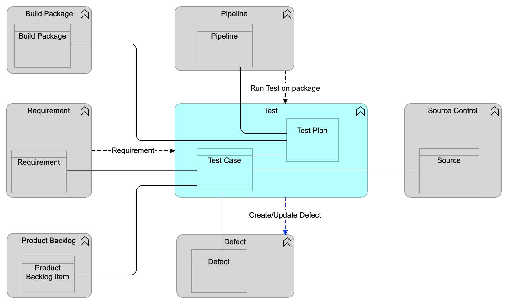
Data Flow Notation indicates a data flow of requirement data from the Requirement functional component to the Test functional component. There is also a data flow of test result data from the Test functional component to the Defect functional component. These two flows are used to maintain the relationships between the corresponding data objects.
Finally, there is a data flow from the Pipeline functional component to the Test functional component indicating that the Pipeline functional component engages with the Test functional component. The data flow indicates that a specific test needs to be triggered for execution.
| In diagrams for a specific functional component, like Test in Data Flow Notation, we only show data flow in and out of that component. For instance, there is a data flow between Pipeline and Build Package, which is not shown in this diagram but can be seen in Build Package Functional Component Model and Pipeline Functional Component Model where Build Package and Pipeline is documented. |
As is seen in Data Flow Notation, an arrow is used for representing data flows. As indicated, there are two types of data flow:
-
System of record data flows: these establish system of record integrations and are essential for maintaining a consistent and traceable information model for digital management
Typically indicating that the data object in the respective components are interlocked
-
System of engagement data flows: these represent integrations that are useful for efficiently implementing the value streams that orchestrate the use of many of the IT4IT components
In the above example the data flow from Test to Defect is a system of engagement data flow.
System of engagement data flows are marked in blue, as opposed to system of record data flows that are black.
System of Record Integration
In Level 1, key data objects and their relationships are introduced. In Level 2, how data objects are consumed or created/updated by the value streams is described. In Level 3, all the necessary key data objects and relationships are defined to form a consistent and traceable information model for managing Digital Products.
In order for the system of record relationships to be sustained over the course of the product lifecycle, integrations between functional components controlling the key data objects must be well defined. This requires that some data flows need to be “refined” into system of record integration specifications. These specifications become part of the normative IT4IT Standard.
For a data flow to be refined into a system of record integration, the following conditions must be satisfied:
-
The data flow creates a relationship/dependency between two data objects in the functional components involved in the data flow
-
The two data objects must have a direct relationship to be maintained
-
The lifecycles of the two data objects are interlocked; updates to one data object can have consequences on the other data object
The reason for defining these integrations as part of the architecture is to ensure the integrity of the system of record fabric and the service model. IT organizations are likely to implement products from multiple suppliers for their IT4IT Reference Architecture, and without this specification there is no way to ensure consistency in data flows.
A system of record integration is depicted in Data Object State Model Dependency Illustration. This figure provides an illustrative example that describes the state dependency between the “Event” and “Incident” data objects. Here, Events generate Incidents, which results in a relationship and dependency between these two data objects.

System of Engagement Integration
Relationships are also formed between functional components to enable humans and machines to interact with and/or take action on the data objects. These relationships are called “system of engagement” integrations (experience-centric integration) and are derived from value stream use-cases and user stories. They are offered as guidance rather than prescriptive practices; the intent being to demonstrate to the reader how data object relationships stimulate and/or are affected by human-to-machine and machine-to-machine interactions.
For example, the Incident to Knowledge system of engagement integration “Search Knowledge” (see Incident Functional Component Model) indicates that a common use-case for managing an incident is to look up relevant Knowledge Items based on the Incident information and potentially create a link to the most relevant ones. But unlike a system of record integration we do not specify that there is a long-lived maintained relationship, such as when an incident is updated then the Knowledge Item needs to be updated, or that updates to Knowledge Items should result in updates to the related Incidents.
Notation and Naming
At Level 3, the normative notation depicts system of record integrations using a black dotted line with a solid end-arrow accompanied by the name of the data object that is transferred to create the relationship. No subsequent information is shown as being passed on an ongoing basis to maintain or update either data object. The formal notation in the ArchiMate language uses the collaboration and interaction concepts.
System of engagement integrations use blue dotted lines with a solid end-arrow, and a name that describes the type of engagement or process action responsible for triggering the integration/data flow.