Concepts at Level 1: End-to-End Overview
Abstraction Level 1 is considered the “overview level”. It provides a holistic model of the IT4IT Reference Architecture, introducing the core terms and concepts that underpin the architecture. It depicts, at a high level, the foundational controls an IT organization needs in place to standardize, automate, and generally manage the IT4IT Value Streams.
At this level, six core concepts are introduced that are central to the IT4IT Reference Architecture body of work:
-
Value Network
-
IT4IT Value Streams
-
Management capabilities
-
Functional components
-
Data objects
-
Digital Product Backbone data objects
-
Service Offer Backbone data objects
-
-
Data relationships
Value Network
A Value Network is a construct that defines the relationships across the value-creating functions that deliver value.
Within the IT4IT framework it is used to describe the model of the digital business function. It includes primary activities such as planning, production, consumption, fulfillment, and support. It also includes supporting activities such as Finance, HR, Governance, and Supplier Management.
| The Value Network concept is an evolution of the Value Chain concept from Michael Porter’s book Competitive Advantage: Creating and Sustaining Superior Performance [Porter 1998]. |
The Value Network concept breaks with the waterfall-oriented aspect of the original Value Chain construct and makes each value-creating activity both consuming and value-producing to potentially many other activities.
Value Stream
A value stream describes the value-creating activities for discrete areas within the Value Network where some unit of net value is created or added to the Digital Product as it progresses through its lifecycle. The IT4IT Reference Architecture defines seven essential value streams for digital management. These are referred to as the IT4IT Value Streams; see IT4IT Value Streams Model.
Notation and Naming
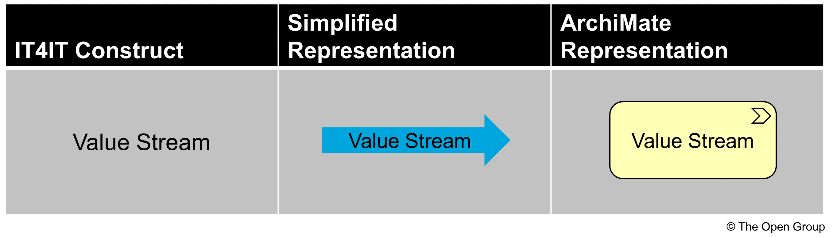
The IT4IT Standard has both a simplified notation and a notation aligned with the ArchiMate language, as pictured in Value Stream Notation.
As a general rule, the IT4IT Value Streams are named using:
-
A verb that describes the essence of what the value stream is doing
Note that occasionally the verb can be used in connection with the essential (backbone) data object that the value stream works on. This is only in the description, and not the normative name. Also note that this document breaks with the tradition of using a x2y notation like “Detect to Correct”. This brings it more in line with how similar value streams are named in some Agile frameworks. Finally note that the value streams are not prepended with the word “continuous”, which is often found in Agile text books. The prepending of "continuous" is considered a maturity construct and should not be part of the name.
Functional Groups
The IT4IT Reference Architecture uses the ArchiMate grouping construct as a way of grouping the functional components and data objects together to provide context for the functionality that organizations must deliver.
This can be used as a basis for capability planning in an organization but the standard does not prescribe what capabilities a Digital Organizations should build.
The normative IT4IT Standard defines a grouping at two levels:
-
Level 1: five high level groups of functionalities
-
Level 2: further decomposition into 14 groups
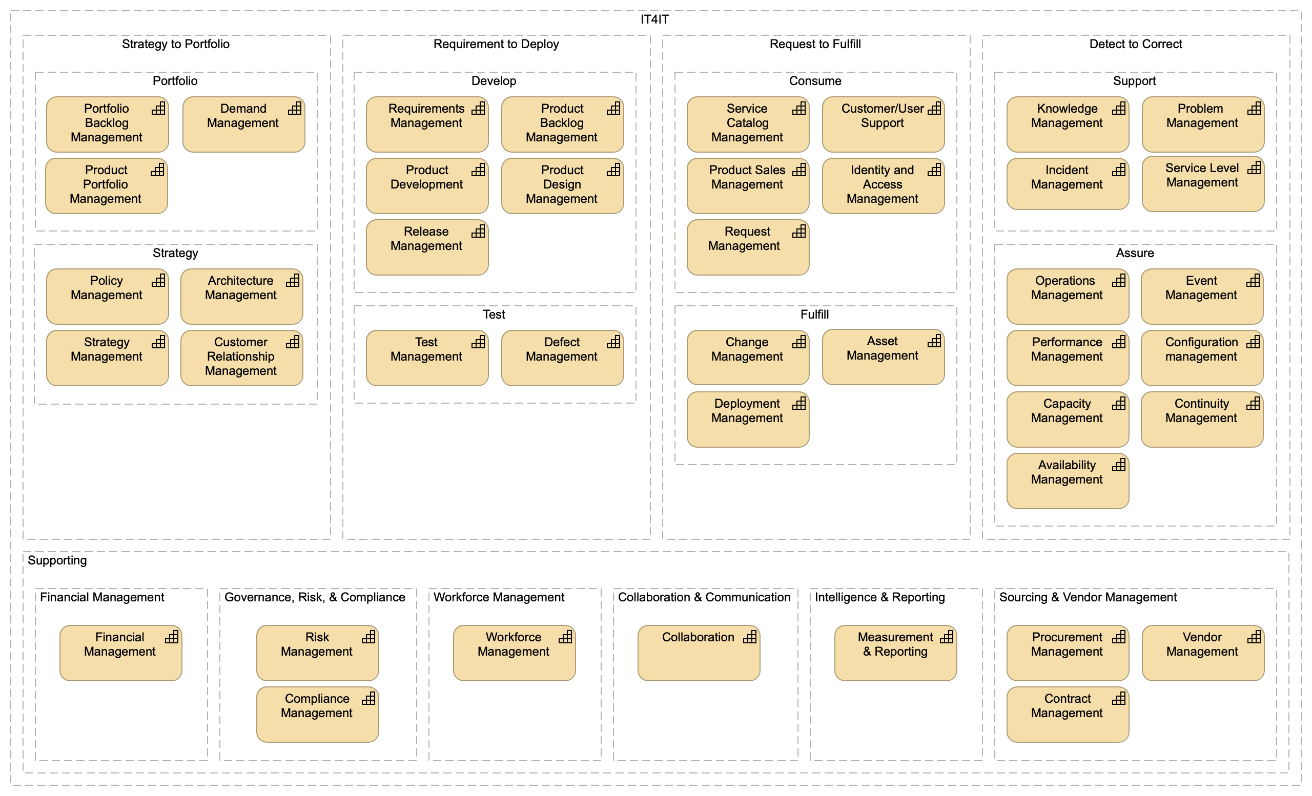
At Level 1, the IT4IT Standard defines the following functional groups:
-
Strategy to Portfolio (Plan)
-
Requirement to Deploy (Build)
-
Request to Fulfill (Deliver)
-
Detect to Correct (Run)
As well as the Support functions that are referenced but are not normative definitions in the IT4IT Standard.
Each one of these is then further decomposed at Level 2 to provide more structure to the reference architecture.
Note that the groupings are simply a way of grouping related functional components together to be able to talk about functionality in a more abstract way, such as Support functions, Assure functions, or simply Run functions. When the IT4IT Reference Architecture is used to implement digital management in a real organization it is necessary to also do capability mapping, as it remains an important activity for organizations. Detailed capabilities that would include process and people aspects are not included as part of the normative documentation. Instead, other documents (guidance documents) will provide this level of detail. The objective of the IT4IT Reference Architecture is to convey, in a prescriptive fashion, the key data objects, relationships, and components that are foundational for all IT organizations. Example of Level 1, Level 2 Groups with a Possible Capability Decomposition gives an example of a possible decomposition of the IT4IT normative Level 1 and Level 2 groups into detailed capabilities.
There is also Supporting Functionality within the Value Network model, such as Supplier & Vendor Management, Workforce Management, and Financial Management. As with detailed capabilities, these do not define the Supporting Functions in details, but do define some of the essential data objects and functional components that are expected from the Supporting Functions in order for the primary functionality and value streams to work.
Notation and Naming
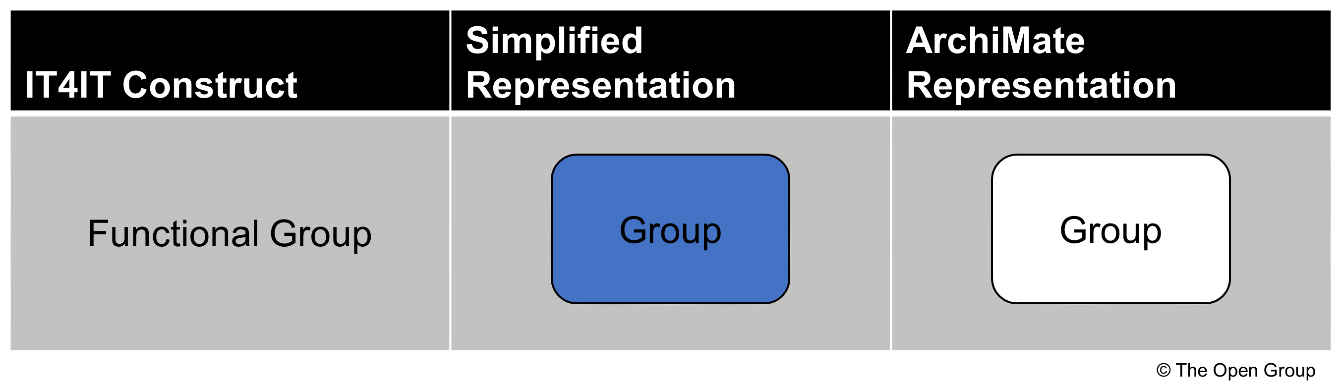
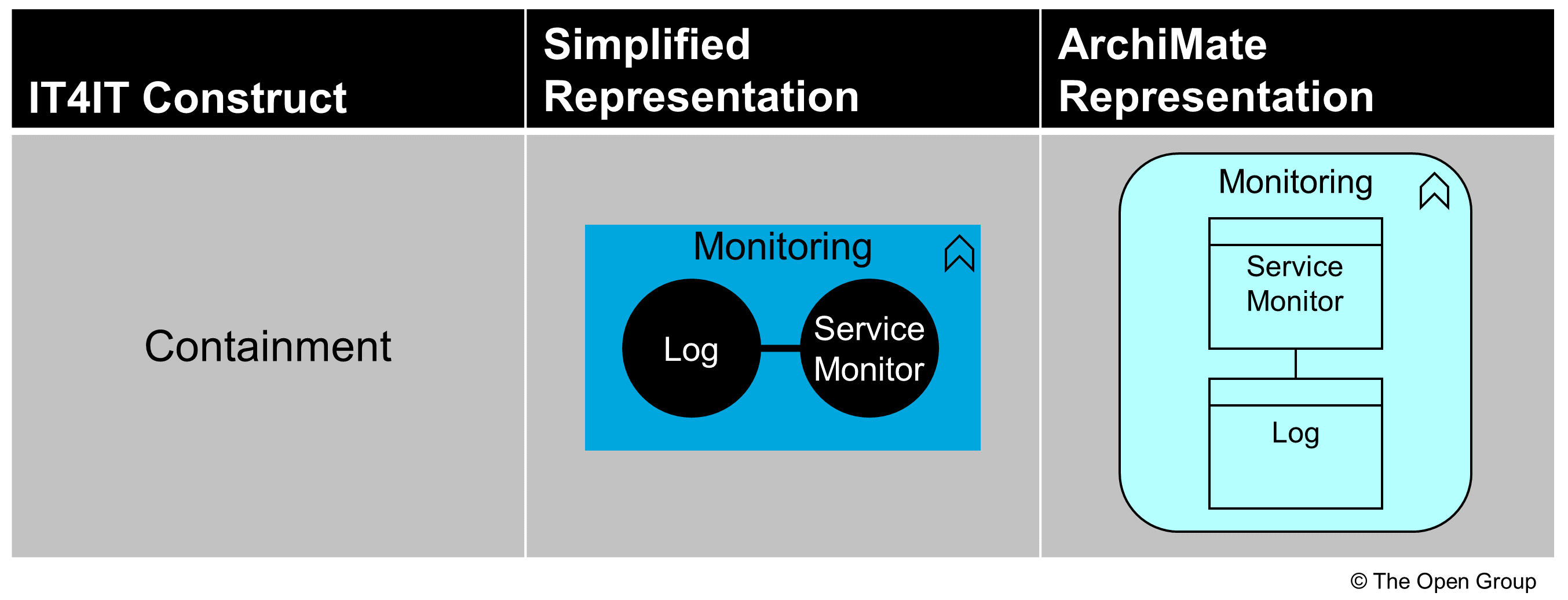
The IT4IT Standard uses the ArchiMate grouping types and a containment notation to indicate decomposition and to illustrate which functional components support a given functional group.
| Example of Level 1, Level 2 Groups with a Possible Capability Decomposition illustrates a number of capabilities. This is for illustration, and not normative. The IT4IT Standard only defines a general grouping of functionalities and is not defining a formal capability model. |
As a general rule, the IT4IT Functional Groups are named using:
-
A verb that describes the essence of what the group of functions is performing
Functional Component
A functional component is the smallest unit of technology that can stand on its own and be useful as a whole to a Digital Practitioner (or IT organization). It has defined input(s) and output(s) that are data objects and has an impact on a key data object that it controls. Typically, a functional component controls and/or manages a single key data object, but this is not dictated by the architecture; it can control several, especially if they are intrinsically connected.
Examples of functional components include Event, Product Backlog, Defect. The IT4IT Reference Architecture contains only those functional components that have an impact on key data objects. There will be other technology components and management systems used by IT organizations in the normal course of business, but that are not considered part of the prescriptive IT4IT Reference Architecture. Examples of these types of components could include Corporate Finance systems, HR applications, and Contract Management systems. These will be supplied by the Supporting Capabilities. These are not normative but in some cases the reference architecture will make reference to those.
Notation and Naming
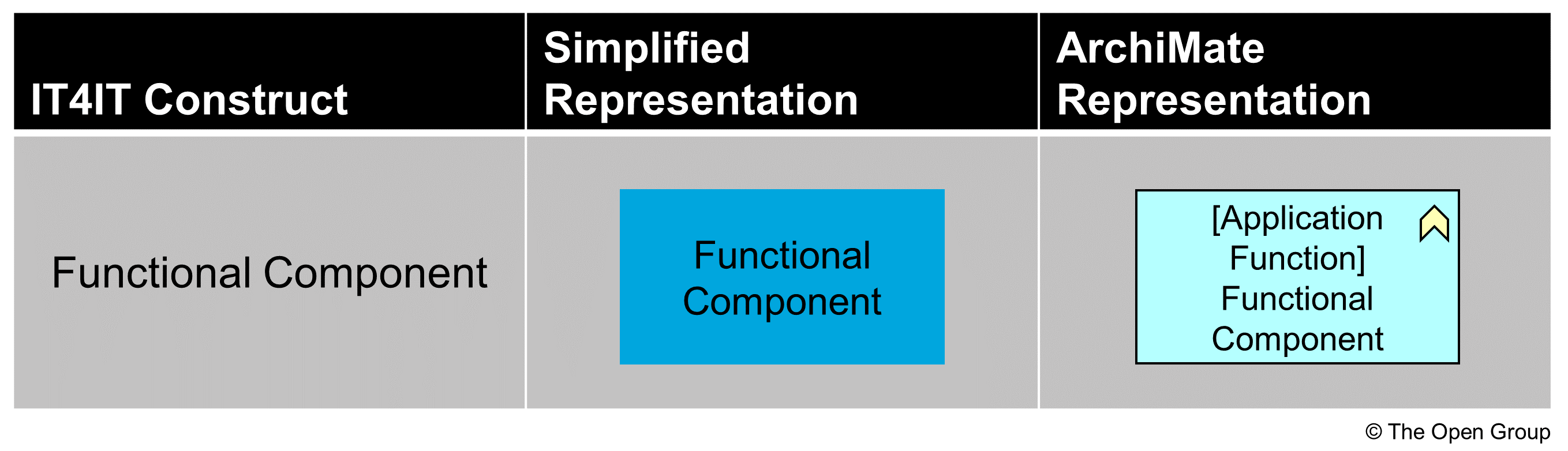
The IT4IT Reference Architecture uses both a simplified and an ArchiMate notation style. At Level 1, the informal notation renders primary functional components as blue rectangles (see Functional Component Notation). Secondary functional components are rendered as gray rectangles. Functional components are represented formally in the ArchiMate language using the “Application Function” type.
As a general rule, the IT4IT Functional Components are named using:
-
A noun or a noun with a qualifier that describes the essence of what the functional component is managing
Occasionally the name is appended with the word “component” as a shorthand for “functional component”.
Key Data Object
A Key Data Object represents data (records, information, and so on) that annotate or model an aspect of a Digital Product being planned, developed, offered, or consumed. Data objects can take a digital or physical form and can be comprised of structured, semi-structured, or unstructured data. Our definition of Key Data Object is aligned contextually with the Object Management Group® (OMG®) definition of artifact. In UML, the OMG defines artifact as:
“… the specification of a physical piece of information that is used or produced by a software development process, or by deployment and operation of a system. Examples of artifacts include model files, source files, scripts, and binary executable files, a table in a database system, a development deliverable, or a word processing document, a mail message.” [UML]
Examples of data objects include incident records, training videos, requirements documents. These types of data objects contribute in some way to define and control a Digital Product over the course of its lifecycle. There are also “special” data objects that represent an abstraction or view of a specific product; for example, a system diagram, release package, or a binary executable file; this provides a “view” of a product to various personas at different stages of the product lifecycle. These special data objects and their relationships form a “backbone” that binds together all of the information needed to offer and manage a Digital Product, thus they are referred to as Digital Product Backbone data objects.
The central focus of the IT4IT Forum has been to identify the data objects that play a “key” role in the product lifecycle. In other words, the reference architecture focuses exclusively on the data objects that are mandatory for ensuring end-to-end traceability of the product lifecycle operationally and/or financially. There are other data objects used across the digital landscape to facilitate various needs or activities (e.g., company-specific processes), but these are considered to be secondary or auxiliary and outside the prescriptive control of the IT4IT Reference Architecture.
Notation and Naming
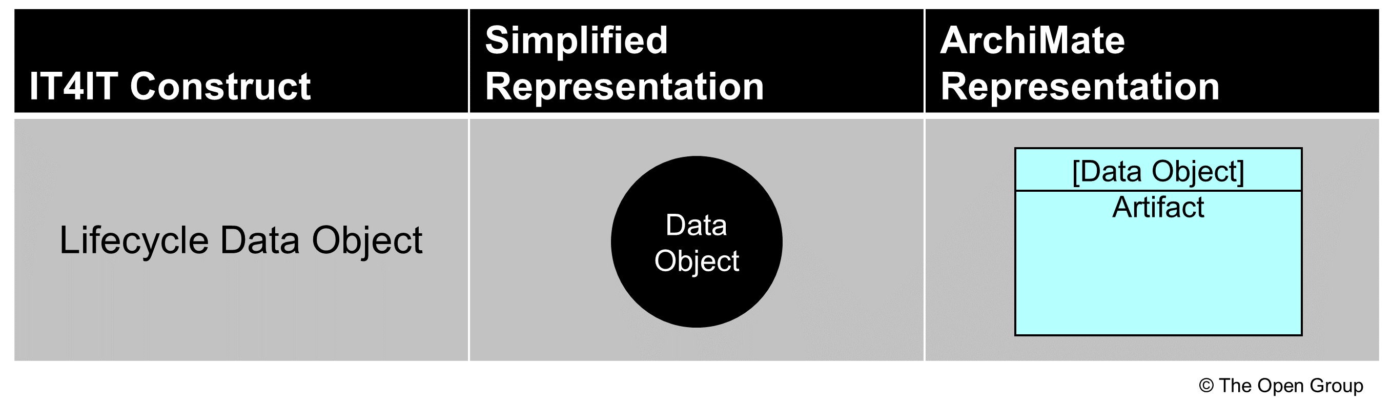
The IT4IT Reference Architecture utilizes both a simplified and an ArchiMate notation for data objects so that the work can be easily understood by both architects and non-architects. In the Level 1 model, a simplified notation that depicts data objects as circles is used. Color is used to specify whether a data object is key data object (black) or a backbone data object (orange). Data objects are modeled formally in the ArchiMate language using the “Data Object” type, as shown in Key Data Object Notation.
Text is also important in communicating the concepts represented in the model. According to dual-coding theory, using text and graphics together to convey information is more effective than using either on their own. Further, the IT4IT Reference Architecture attempts to avoid using text that creates collisions between architectural layers (e.g., business function, data, and implementation layers). Level 1 introduces naming conventions for data objects that are rooted in the well-known IT frameworks and standards.
While a functional component may control one or more data object types, a single data object can only be controlled by one functional component. To communicate this visually, a notation that embeds the “controlled” data object in the functional component is used; see Functional Component Data Object Notation.
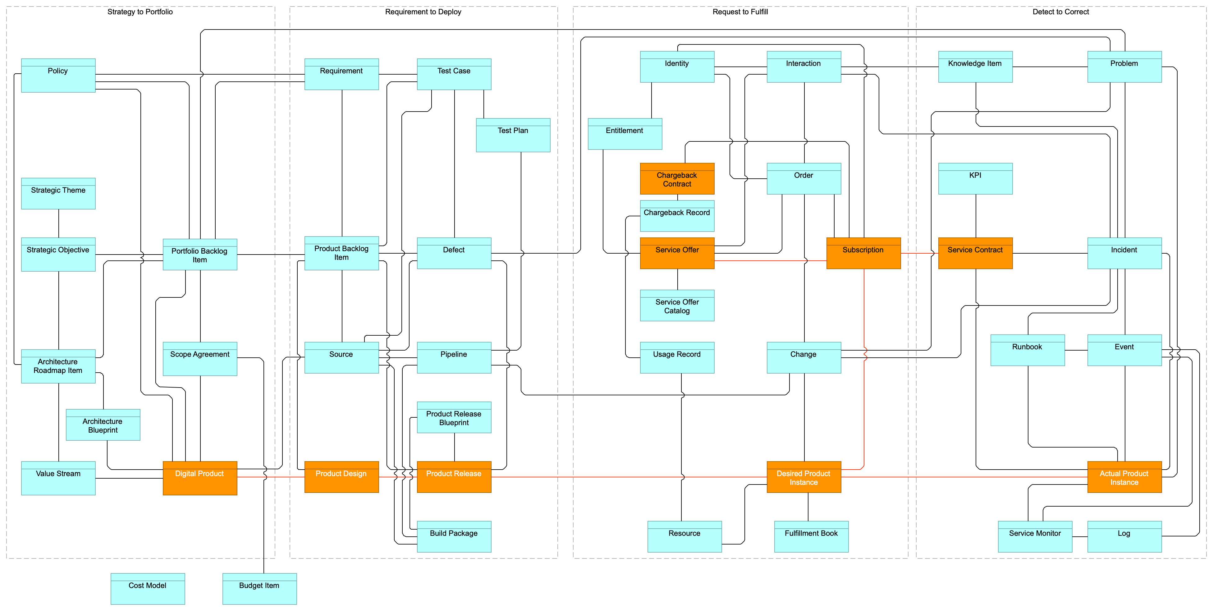
Diagrams can be complex and require clear “visual syntax” to help the reader interpret the elements and their relationships. For that reason, the IT4IT Reference Architecture at Level 1 is depicted without data flows and a reduced set of data relationships; see The IT4IT Level 1 Functional Diagram.
As a general rule, the IT4IT Data Objects are named using:
-
A noun that describes the essence of what the data object is controlling
System of Record
A system of record is a synonym for a system that contains and/or controls authoritative source data.
The key data objects represent the authoritative source data and/or master data for managing digital. In IT, “system of record” is a term that is commonly used as a synonym for an authoritative source system.
Relationships
An important aspect of the IT4IT Reference Architecture is to define not only the data objects but the essential relationships between them. The data objects, combined with their relationships and inter-dependencies, form the “system of record fabric” for digital management (see Relationship Notation and IT4IT End-to-End Traceability (System of Record Fabric)).
Note that in this document there are no defined “reflective” relationships, where a data object can relate to other data objects of its own type; for instance, the Digital Product data object relates to all the Digital Products on which it depends, the Service Offers can represent a hierarchy of offers, or Events can relate to Events to represent correlation. A future version of the IT4IT Standard will include these relations.
Notation and Naming
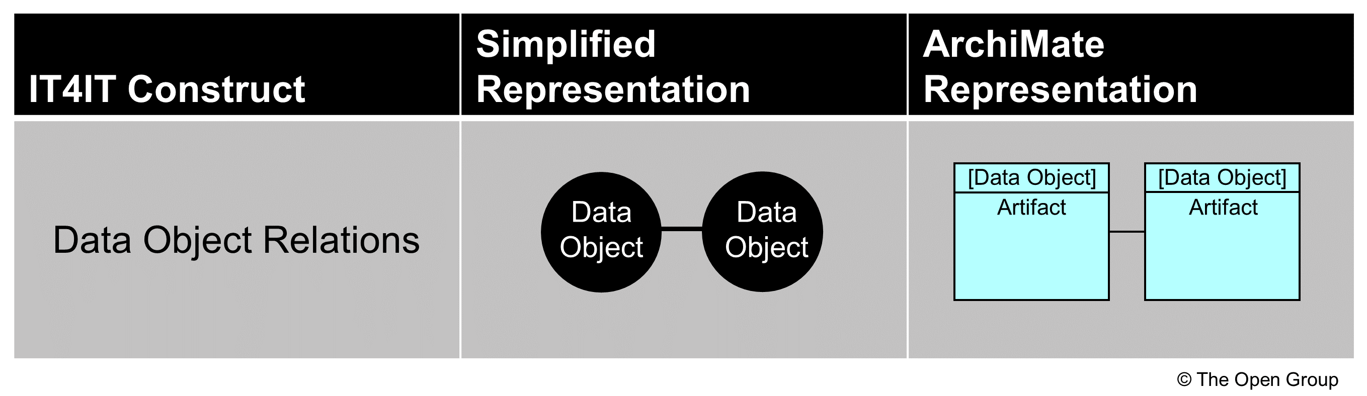
Abstraction Level 1 expresses essential relationships as lines between the participating data objects. Here, the simplified and ArchiMate notation are identical; a line connecting one data object with another.
Compliance with the prescribed system of record relationship mapping will ensure end-to-end traceability operationally and financially, and ensure Digital Product model integrity can be maintained across the lifecycle. This also eliminates the confusion and collisions that result from process re-engineering efforts that frequently occur within the various IT functions.
Digital Product Backbone Data Objects
The Digital Product Backbone data objects are key data objects in the IT4IT Reference Architecture that annotates an aspect of the Digital Product model in its planning, development, consumable, or running state. These data objects and their relationships form the Digital Product Backbone, which provides a holistic view of a Digital Product and includes the Digital Product, Product Design, Product Release, Desired Product Instance, and Actual Product Instance.
The IT4IT Standard collectively refers to all Digital Product Backbone data objects as the “Digital Product Backbone”.
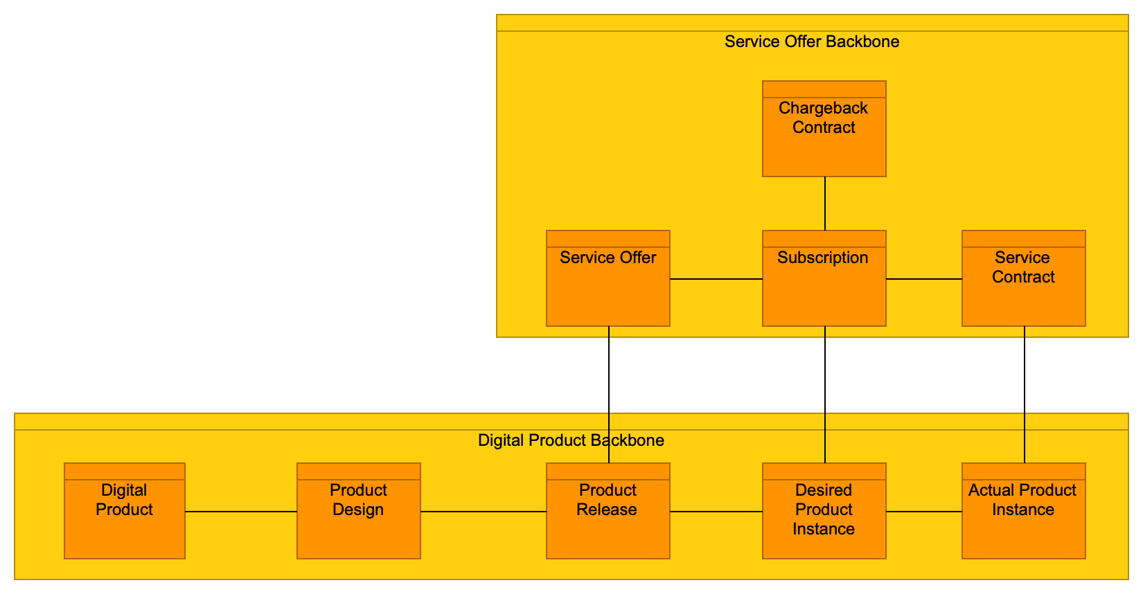
Service Offer Backbone Data Objects
The Service Offer Backbone data objects are key data objects in the IT4IT Reference Architecture that control and define the consumption of a Digital Product. These data objects and their relationships form the Service Offer Backbone and include the Offer, Subscription, Chargeback Contract, and Service Contract data objects.
The IT4IT Standard collectively refers to to all the Service Offer Backbone objects as the “Service Offer Backbone”; see IT4IT Digital Product Backbone and Service Offer Backbone Data Objects. Note that IT4IT Digital Product Backbone and Service Offer Backbone Data Objects is an abstraction and the relation between Service Offer and Product Release is via the Product Release Blueprint.
Level 1 ArchiMate Model
With the above definitions of the simplified functional component, data object, and ArchiMate notation, IT4IT Level 1 can be visualized in IT4IT Level 1 in ArchiMate Notation, which can be compared to the simplified notation in The IT4IT Level 1 Functional Diagram.
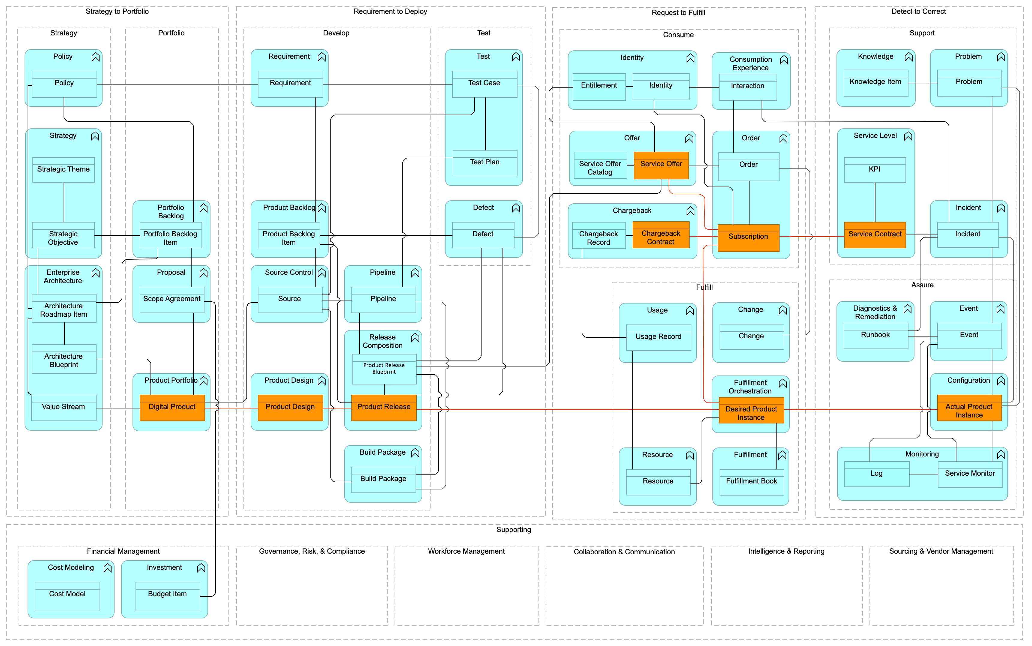
Note that the Level 1 figures are abstractions, created for easy readability. This implies that not all the relations of the formal model are shown. For all the IT4IT data object relations, see the diagrams in the definition of the functional groups: Strategy to Portfolio Functions Model, Requirement to Deploy Functions Model, Request to Fulfill Functions Model, Detect to Correct Functions Model.